


RESTORATION PROJECT - 4
October 2007
As the plan is to finish with a machine closely resembling the GP200 I bought new in
November 1970 from Seals of Southsea, it has to be a 200cc machine and as this one
started out as a 150cc, I have purchased a new 200cc crankcase, barrel and piston. The
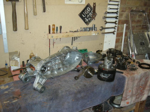
barrel and piston are basic items to keep things as close to original as possible. Here's
most of the parts ready for assembly.
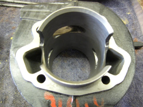
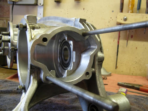
I am not going to tune the barrel but just match up all the ports to crankcase and
manifolds as required. Here's an image of that work pretty much complete.
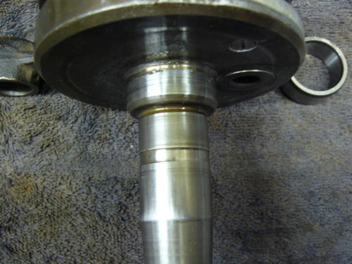
I was going to re-use the original crankshaft but when I came to fit the mag side
bearing, the inner track just fell onto the crankshaft and as it's supposed to be an
interference fit I decided I would be happy with a new crank anyway. here's the
offending item.


A standard crankshaft was sourced and very fine it looked too, this time the mag side
track was a nice tight fit and I have piece of mind knowing that I have a good quality
crankshaft that should last many a year.
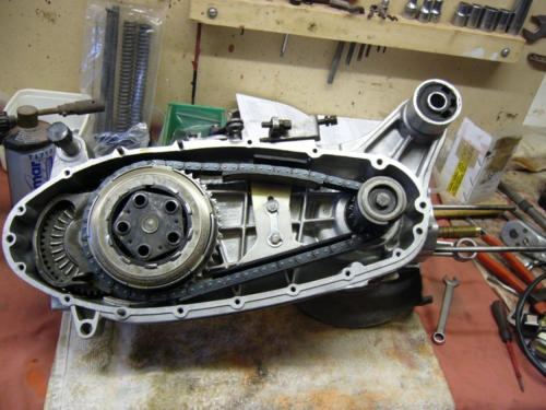
I guess it goes without saying that all new bearings, oil seals and gaskets were fitted
throughout the engine; but I've said it anyway. On the transmission front, new clutch
plates and circlip fitted, the inner and outer clutch housings needed some tidying up to
remove burrs. New top and bottom chain guides, the chain and original engine sprocket
were retained. I was going to fit a GP200 gearbox and replace the original, along with
new 47/18 sprockets and chain, however at the moment I am going to reuse the
original setup with a view to making this change perhaps later on.
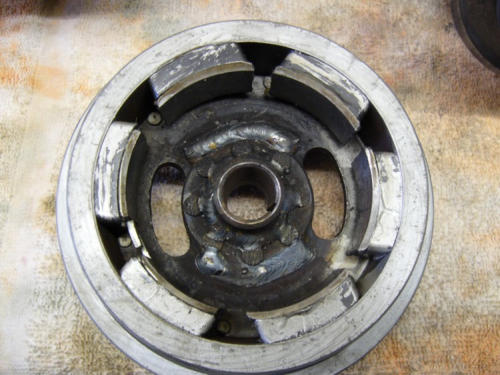
A new ignition system was next on the agenda as the original was a 6V points system
and I wanted to upgrade to 12V electronic. There are many sources from which to
purchase electronic ignition systems, in the end I decided on MBD as they beef up the
flywheel in a couple of areas and also provide a wiring loom that does away with the
need for a junction box. The flywheel does not look very pretty but it will hopefully be
more durable and reliable due to the modifications.
The Stator plate also receives some attention from MBD, tightening the rivets holding it
all together and bonding earth points.
On assembly I noticed that the flywheel seemed to be just touching one of the iron
cores at one point when rotated by hand, this was only very slight and could only really
be heard rather than felt. However I felt it would be best to check this with Mark at MBD
just to be on the safe side and I am pleased to say that he did indeed assure me that
this was not unusual and was most likely due to a rather thick coating of varnish.
MBD provide comprehensive instructions with their electronic ignition system to help you
set it up correctly; top marks for this.
So using the instructions I set up marks on the Mag flange to indicate top dead centre,
21o and 19o BTDC. MBD recommend now using 19o rather than what used to be
standard for a GP200, 21o, due to the difference in unleaded fuel. MBD detail several
ways of setting up the marks, I used both the dial gauge and degree wheel method to
cross reference and check my accuracy. Final setting of the ignition timing will have to
be done with the use of a strobe gun, once the engine is running.

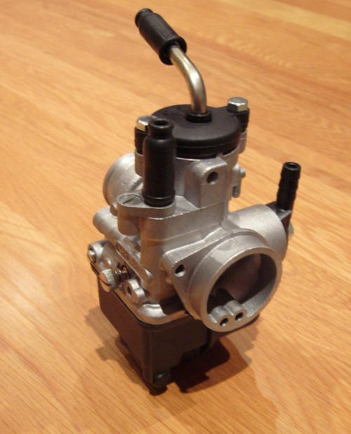
One area of departure from standard is to be the fitting of a Dellorto PHBL 25
Carburetta, purchased from MBD who again provided very comprehensive instructions
for setting up and running.
I will be retaining the air filter box and hose which will keep it looking nice and standard
and have removed the internal baffle as advised in the instructions when fitting a larger
than standard carburetta but retaining the standard air filter box etc.
To complement the Dellorto I am also fitting a large bore Ancilloti exhaust. For some
reason I decided to make the fairly expensive purchase of the Ancilloti over other large
bore exhausts, however I am not really that impressed with the product. I am not keen
on the fact that the 'U' tube is made up of two pipes of different diameter, so there is a
'step' about half way round. The other issue is the fact that in manufacture the main box
was not cut properly to meet the cone where they are joined.
This can be seen in the image on the right and is in fact worse than the image portrays.
Exhaust gasses flowing into the exhaust are obstructed by parts of the main box that
have not been trimmed properly to match the cone! I spoke to the dealer who quoted
the figures apparently achieved on a dynamometer; I wonder whether these were
achieved with a golden sample? Whatever, with just a little more attention to detail it
could be so much better.
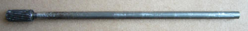
I just couldn't bring myself to fit the exhaust to my scooter as supplied so I took a trip
to B&Q, bought a rotary file and a piece of 6mm I.D. tube; cut this to 300mm in length
and then soldered the rotary file into the tube, so it looked like this:
I then spent the next hour grinding out all the excess material to improve flow into the
exhaust.

December 2007
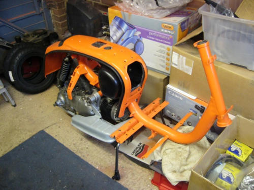
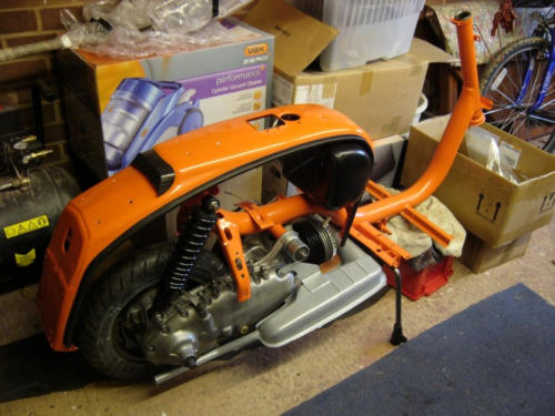
After the minor drama of the exhaust the engine was at last in one piece and ready to
go into the frame; once in I also tried the exhaust to see if this fitted ok, which indeed it
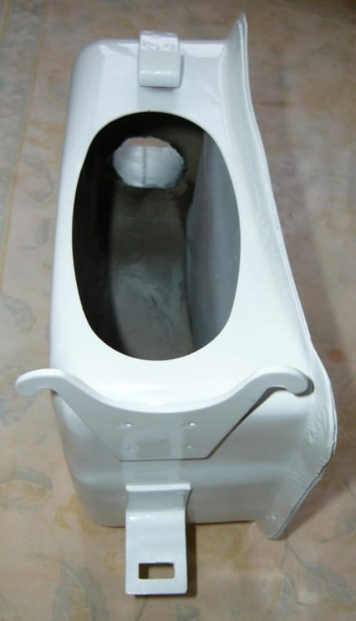
did. All this can be seen in the next two images and by this time the toolbox has also
been slotted in. As you can see the toolbox is black, this is so that it resembles the black
plastic toolbox I had on my original GP200, although this one is in fact metal.
So now it's down to wiring, cables and bodywork.